08 Jul 2014
通常在Android上使用ndk-build编译C++代码。但大多开源库中并没有提供Android.mk文件。
这里只能使用单独的toolchain来编译。关于toolchain可参考
http://blog.csdn.net/smfwuxiao/article/details/6587709
准备工作
创建一套工具链
/Users/chaohan/Documents/android-ndk-r9d/build/tools/make-standalone-toolchain.sh --platform=android-8 --stl=stlport --install-dir=/Users/chaohan/Documents/android-8-toolchain
由于我的代码使用了stlport,这里增加--stl=stlport参数。生成的工具链的位置通过--install-dir设置。
设置环境变量
export PATH=$PATH:/Users/chaohan/Documents/android-8-toolchain/bin/
下载代码
git clone https://github.com/OSGeo/gdal.git
代码中的config.sub config.guess不认识android环境,这里需要更新
cd gdal
rm config.sub config.guess
wget http://git.savannah.gnu.org/cgit/config.git/plain/config.sub
wget http://git.savannah.gnu.org/cgit/config.git/plain/config.guess
编译
CFLAGS="-mthumb" CXXFLAGS="-mthumb" LIBS="-lstdc++"  ./configure --host=arm-linux-androideabi --prefix=/Users/chaohan/Documents/Git/gdal/out --without-gif --without-jpeg --with-threads --with-ogr  --with-geos --with-libz=internal

make

make install
我这里make时遇到isinf不认识。通过修改cpl_port.h文件去掉,不影响大局。
使用
在Android.mk中增加
定义预编译静态库
include $(CLEAR_VARS)
LOCAL_MODULE := gdal
LOCAL_SRC_FILES := libgdal.a
include $(PREBUILT_STATIC_LIBRARY)
设置依赖
LOCAL_STATIC_LIBRARIES := gdal
参考
https://github.com/nutiteq/gdal/wiki/AndroidHowto
http://trac.osgeo.org/gdal/wiki/BuildingForAndroid
问题和感想
在编译过程中遇到很多问题。主要的问题是
-
运行configure出错,不认识arm-linux-androideabi。通过更新config.sub config.guess解决。
-
stl版本冲突。默认toolchain使用gnustl,而我的库使用stlport。通过在make-standalone-toolchain指定--stl=stlport解决。
-
第三方库重定义。gdal包含gif、jpeg等库,我的库也包含它。通过在configure时--without-gif --without-jpeg去除。
真心觉得C++的编译环境复杂,不同平台有不同的编译工具。从make、autoconf、cmake、ndk-build、gyp等脚本到vs、xcode等IDE,用起来真是有各种坑。
希望C++也能有个Maven、cocoaPods、npm之类的工具解决软件包之间的依赖问题。
18 Jun 2014
上周,Ansis解释了在Mapbox GL标签被放置的方法,但一旦我们知道在何处放置标签,我们还是要弄清楚如何绘制他们。
甚至在2014年,OpenGL诞生后超过二十年,渲染文本也是不容易的,因为OpenGL的只能画出三角形和线条。地图渲染文本是更加困难的,因为我们需要在许多不同大小的字符,当用户旋转地图时文本位置的每帧都会变化。此外,我们需要画文本光晕已得到更好的对比度。
使用字形图集
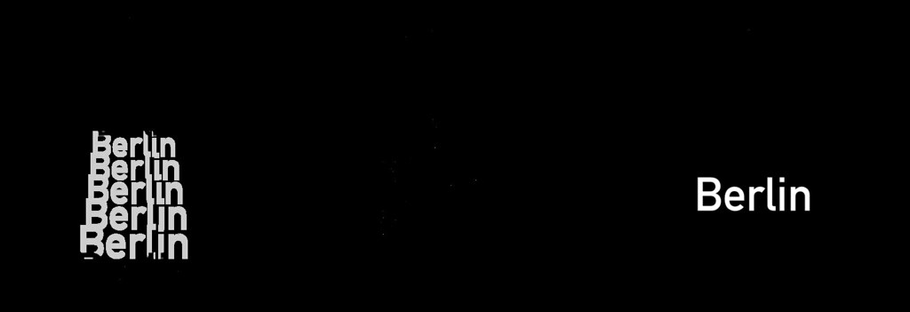
对于栅格化文字一般是使用开源库FreeType。绘制文本通常的工作方式是通过FreeType在临时缓冲区生成字形的单色位图,然后将缓冲区中的像素逐个混合目标位图正确的位置上去。这意味着,我们可以预先将需要的所有字形的染到一个共享的纹理中,称为纹理图集,然后为每个字形创建两个三角形映射到纹理上。Nicolas Rougier的freetype-gl也是通过这种方法实现的。
这很好的工作,直到你开始旋转文字。虽然OpenGL的线性插值是相当好的,但它仍然看起来相当模糊的,所以只是旋转字形并不能满足我们。
Signed Distance Fields
Distance fields (or distance transforms) have been around for ages and have lots of useful properties. In a distance field, every pixel indicates the distance to the closest “element”. Valve introduced the approach of using distance fields for rendering sharp decals in computer games a couple of years ago. And we decided to do just that when rendering glyphs as well.
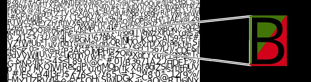
To render text with signed distance fields, we create a glyph texture at font size 24 that stores the distance to the next outline in every pixel, rather than the actual value itself:
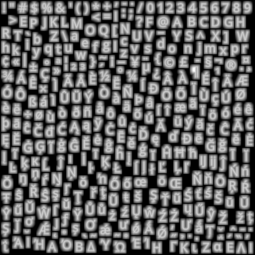
Inside of a glyph, the distance is negative; outside it’s positive. As an additional optimization, to fit into a one-byte unsigned integer, we’re shifting everything so that values between 192 and 255 indicate “inside” a glyph and values from 0 to 191 indicate outside, plus we clamp the overflowing values. This gives the appearance above of a range of values from black (0) to white (255). In essence, we are using the pixel color values in the texture as a measure of distance from glyph edges.
Like in the previous technique, we create two triangles to form a quad and assign the corresponding texture coordinates so that the distance map of that glyph gets mapped onto that rectangle.
We enable OpenGL’s linear interpolation so that we get a smoothly scaled image. Then, the important part is the alpha test. Depending on how far we want to buffer the glyph, we choose a cutoff value and assign 1 as the alpha value to all pixels that are within the glyph outline and 0 to the ones outside. To get an antialiased look, we’re creating a small alpha gradient around the cutoff value with the smoothstep function. The entire pixel shader looks like this:
precision mediump float;

uniform sampler2D u_texture;
uniform vec4 u_color;
uniform float u_buffer;
uniform float u_gamma;

varying vec2 v_texcoord;

void main() {
    float dist = texture2D(u_texture, v_texcoord).r;
    float alpha = smoothstep(u_buffer - u_gamma, u_buffer + u_gamma, dist);
    gl_FragColor = vec4(u_color.rgb, alpha * u_color.a);
}
你可以在这个演示试试文本渲染。
Using signed distance fields for font rendering has a few advantages:
- Free accurate halos by simply changing the alpha testing threshold.
- Arbitrary text rotation.
- Arbitrary text size, though it starts looking a bit off at very large text sizes.
- A bitmap of a 24px glyph is about 20% smaller than the vector representation of that glyph.
There are a few minor drawbacks too:
- Text appears a little more rounded.
- No support for font hinting.
Font hinting changes the glyph outlines so that they fit better in a pixel grid, which is especially useful when rendering small text. However, FreeType disables hinting anyway as soon as you rotate a glyph with a transformation matrix. Additionally, many of our maps are being displayed on very high density (high-DPI or “retina”) screens built into smartphones or tablets, so hinting is much less important on these screens.
原文:https://www.mapbox.com/blog/text-signed-distance-fields/
17 Jun 2014
好的地图标签应该是在介于一个邋遢的地图和一个美观的地图之间的。标签必须清楚地识别功能,同时不遮挡图。
The normal requirements for map labelling are to place labels as clearly as possible without any overlap. Regular maps just need to avoid label overlap for a single, fixed zoom level and rotation.
在Mapbox GL中好的标签位置是一个需要解决的困难问题。我们标签需要在任何缩放和旋转时工作。我们需要标签位置是连续的,缩放或旋转时标签不要跳来跳去。我们标签需要能无缝的跨越瓦片。我们需要支持在缩放时改变字体大小。并且一切都要快速。
Placement needs to support both horizontal labels, as well as curved labels which follow a line. Both types of labels need to behave smoothly when zooming and rotating. Labels can never overlap, even when rotating. Horizontal labels stay horizontal and curved labels rotate with the map. Labels are flipped to avoid being drawn upside down and curved labels smoothly slide along roads.
There is plenty of academic research on label placement, but most of this applies to maps with fixed rotation and with separate zoom levels. Dynamic maps with continuous zooming, panning, and rotation need a completely different approach. Our implementation expands on a paper by Been and Yap that establishes four ideal requirements for continuous and interactive labelling:
- 标签不应该在放大时消失,在缩小时出现。
- 标签不应该在平移时消失或出现,除非滑出视图。
- 标签不应该跳来跳去,而是应该被锚定。
- 标签的位置应该是确定的,无论你怎么到当前视图。
The paper provides guidance on implementing this for horizontal labels, but we go further by supporting rotation and curved labels.
我们的实现有两个步骤:
- 预处理
- 渲染
The rendering step needs to be fast so that Mapbox GL can rerender the entire map every frame for smooth interaction. Most of the placement work happens in the preprocessing step:
- 为每个标签生成锚点。
- 计算相对于锚各个字形的位置。
- 计算该标签和符号可以没有重叠显示的缩放级别。
- 计算标签可以显示的旋转范围。
生成锚点
Each label has an anchor. An anchor is the point at which a label is positioned when zooming or rotating.
Labels for point features have a single anchor, the point.
For lines, we want to show multiple labels so we interpolate along the line adding an anchor every x pixels. Distance between labels changes when zooming, so we add a minimum zoom level for each anchor to maintain appropriate spacing. Fewer labels are shown at lower zoom levels and more appear as you zoom in.
生成每个锚定位字形
For each piece of text we already have a list of glyphs and their positions, but these positions need to be adjusted for curved labels.
During the render step we can only shift glyphs along a straight line. To draw curved text we need to add multiple copies of glyphs — one for each line segment a glyph appears on. Each of these glyphs have minimum and maximum zoom levels that hide the glyph when it slides off the end of a segment so that only one instance of each original glyph is shown at the same time.
Usually these glyphs are completely hidden when out of range, but here they are shown with a reduced opacity:
限制缩放范围
To avoid label collisions, we need to restrict the zoom level at which a label is first shown. As you zoom in, labels get spaced further apart, opening room for new labels. Once a label is shown, it will not be hidden as you zoom in.
We use an R-tree that contains already-placed labels to narrow down which labels might collide. We then calculate the zoom level at which the two labels will fit side-by-side. It is safe to show the label for any zoom level higher than this one.
限制旋转范围
The next step is calculating how far the label can be rotated before it collides with other labels. There are two types of collisions: a curved label colliding with a horizontal label, and a horizontal label colliding with a horizontal label.
水平-横向碰撞
There are eight possible angles at which a pair of horizontal labels could collide. Each of these possible collisions is checked with some trigonometry.

弯曲-水平旋转碰撞
A curved-horizontal collision occurs when a corner of one label’s bounding box intersects an edge of the other label’s bounding box. For each of the eight bounding box corners, we calculate the angles at which a circle (formed by that point being rotated around the label’s anchor) intersects the edges of the other box. These are the angles at which a collision would begin and end.
无缝性
Mapbox GL下载当前显示范围和缩放级别的矢量瓦片。当新的瓦片下载完成,它们的标签位置已经被旧瓦片的标签占据,可能需要隐藏让位给一个更重要的标签。这将在尚未实现的步骤由解析处理。
Mapbox GL
访问Mapbox GL博客查看和谈论更多的设计和开发工作。地图文本标注只是设备上实时高品质的地图中的一个小而必要的部分。
原文:https://www.mapbox.com/blog/placing-labels/
13 Jun 2014
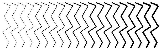
地图大多是由线条以及少量多边形构成。不幸的是,画线是OpenGL的一个薄弱点。GL_LINES绘图模式是有限的:它不支持line joins、line caps、非整数线宽、宽度大于10像素或在一条线上使用不同宽度。鉴于这些局限性,它是不适合于用于高品质地图上使用。下面是GL_LINES的一个例子:
此外,OpenGL的抗锯齿(多重采样抗锯齿)在不同的设备支持程度不同,或者是质量较差。
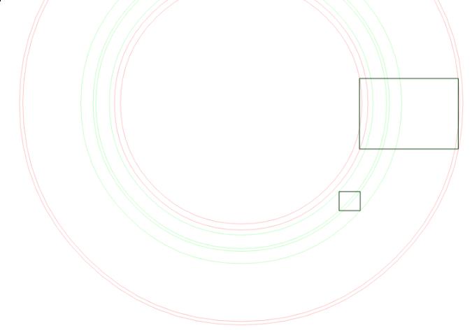
作为替代原生线,我们可以通过镶嵌把线转化成多边形绘制。几个月前,我调查了各种线渲染方法,尝试用六个三角形绘制一条线:
两对三角形的构成两边渐变的边缘,中间一对三角形拼成实线。渐变提供抗锯齿,以使该线有淡入淡出的边缘。当按比例缩小,这将产生高品质的线:
不幸的是,每线段生成六个三角形意味着需要生成8个顶点,这就需要大量的内存。我的试验是每一条线段只有两个顶点,但这样绘制一条线就需要调用3次绘制。为了保持良好的帧率我们需要尽量减少每帧绘制次数。
属性插值的帮助
OpenGL的绘图分为两个阶段。首先,顶点的列表被传递到顶点着色器。顶点着色器基本上是一个小函数,将每一个顶点(在模型坐标系)到一个新的位置(屏幕坐标系),以便您每一帧使用相同的顶点数组,但仍然可以进行诸如旋转、平移,或缩放等操作。
连续的三个顶点形成一个三角形。在这个区域内的所有像素都由片段着色器处理,它也叫像素着色器。顶点着色器的为顶点数组中的每个顶点运行一次,片段着色器为每个像素运行一次,来决定三角形中的像素使用什么颜色。在最简单的情况下,它可能会分配一个固定的颜色,就像这样:
void main() {
    gl_FragColor = vec4(0, 0, 0, 1);
}
颜色顺序是RGBA,所以这个例子所有的片段都使用不透明的黑色。如果我们使用这些多边形绘制线,并且多边形的所有像素渲染流水线使用一致的颜色,那我们还是得到了可怕锯齿线。我们需要一种方法来把多边形的边界像素的alpha值从1渐变到0。在顶点着色器转化顶点坐标时,OpenGL允许我们对每个顶点指定其属性,例如:
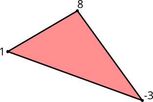
这些属性再交由像素着色器。有趣的部分是这样的:由于一个象素不能直接与单个顶点相关联,该属性根据三角形的三个顶点构成按距离来插值出来:
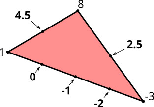
这个插值生成顶点之间的渐变效果。这是我要描述渲染方法的基础。
需求
画线时,我们有几个要求:
- 可变线宽:我们要在每一帧改变线宽,当用户放大/缩小,我们不必将线一遍又一遍镶嵌为三角形。这意味着顶点的位置必须在顶点着色器计算出,而不是预先在场景中设置。
- End caps(对接,圆形,方形):这说明线路两端的绘制方式。
- Line joins(尖角,圆角,斜角):这说明两线之间接缝的绘制方式。
- 多条线:出于性能原因,我们希望与不同的宽度和颜色在一个绘制调用中完成。
线镶嵌
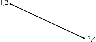
由于我们要动态地改变线宽,我们不能在加载时进行完整的镶嵌。相反,我们重复同一个顶点两次,所以,对于一个线段,在我们的数组有四个顶点(标记为1-4):
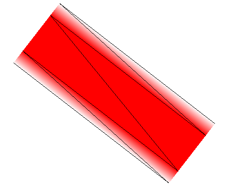
此外,我们计算线段的单位法向量,并将它分配给每一个顶点,与第一个顶点得到正单位矢量,第二个负单位矢量。单位向量是你在这张图片中看到的小箭头:
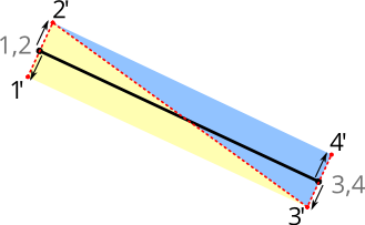
在顶点着色器中,我们在渲染过程中把线宽和顶点的单位向量相乘,并最终有两个三角形,效果如这张照片红色虚线。
顶点着色器看起来像这样:
attribute vec2 a_pos;
attribute vec2 a_normal;

uniform float u_linewidth;
uniform mat4 u_mv_matrix;
uniform mat4 u_p_matrix;

void main() {
    vec4 delta = vec4(a_normal * u_linewidth, 0, 0);
    vec4 pos = u_mv_matrix * vec4(a_pos, 0, 1);
    gl_Position = u_p_matrix * (pos + delta);
}
在主函数中,我们把单位法向量与线宽相乘的到实际的线宽。正确的顶点位置(在屏幕空间)是由模型/视图矩阵相乘得到的。之后,我们添加挤压向量线宽,它是独立于任何模型/视图缩放的。最后,我们乘以投影矩阵得到投影空间中的顶点位置(在我们的例子中,我们使用平行投影,它只是将坐标缩放屏幕空间内,坐标范围为0..1)。
抗锯齿
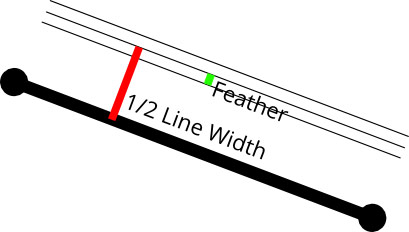
我们现在有任意宽度的直线段,但我们仍然没有反锯齿线。为了实现抗锯齿的效果,我们将使用单位法向量,但这次是在像素着色器中。在顶点着色器,我们只是把单位法向量传递到像素着色器。现在,OpenGL在两个法线之间进行插值,使我们在像素着色器获得两个单位向量之间的渐变。这意味着它们不再单位向量,因为它们的长度小于1。当我们计算该矢量的长度,我们得到该像素到原始线段的垂直距离,在0..1的范围内。我们可以使用这个距离来计算像素的alpha值。如果我们已线宽为参数,在线宽减去羽化feather距离之内的像素,我们只需要分配的不透明颜色(见下图)。在linewidth - feather和linewidth + feather之间,我们指定的alpha值从1和0。并且是比的单位向量远离的片段,我们分配Alpha值为零(此时,还没有像素用到这个属性,但我们很快就会用到它们)。
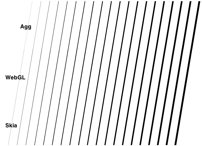
除了线宽外,我们还可以改变羽化距离变得模糊,或阴影。我们可以将其降低到零的到有锯齿线。0.5羽化值会产生和AGG相似常规抗锯齿效果,0和0.5羽化值产生模仿Mapnik伽玛值的结果的结果。
Line Joins
上述方法适用于单条线段,但在大多数情况下,我们需要绘制多条连接在一起的线条。当连接线段,我们必须选择一条线连接样式,并相应地移动顶点:
之前我们使用线的法向量来计算定点的法向量。在线连接的情况下这个方法不在适用,因为需要计算的是定点的法向量,而不是线段的法向量。每个顶点的法向量为两线段的夹角平分线。
在线连接的情况下单位向量也不在适用,因为线连接处顶点的距离比单位距离要长。而不是使用角平分线单位向量,我们只是添加线段的单位向量,从而它既不是单位向量也不是法向量。我把它叫做一个挤压向量。
不幸的是,我们现在有一个问题:挤压载体不再是垂直于线段,所以他们两个人之间的插值不会产生垂直距离。相反,我们引入另一每个顶点属性,纹理法线。这是1或-1的值,取决于正常点是否向上或向下移动。当然,这是不是一个真正的法线,因为它在二维空间中没有方向,但它足以为1和-1之间实现插值来获得我们的抗锯齿直线距离值。
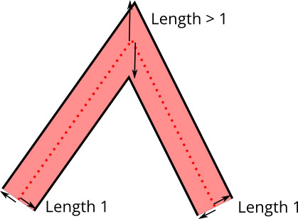
因为我们不希望引入另一个字节,其中我们会有效地只使用一个单一的符号位,我们编码纹理法线到实际的顶点属性。顶点属性使用16位整数(-32768..32767),它们大到足以容纳我们的瓦片0..4095坐标。我们把每个坐标双倍到(0..8190),然后用最低有效位来存储纹理法线。在顶点着色器,我们提取该位,并使用模型/视图矩阵来缩放到我们的坐标系下的实际大小。
为了节省内存,我们用编码,每个轴一个字节的挤压载体,所以我们有一个(整数)范围-128.. 127,每轴。不幸的是,挤出载体可以成长任意长的线连接,因为挤压向量长度增长到无穷大的角度变得更加尖锐。这是一个常见的问题,当画线连接,而解决方案是引入一个“斜接限制”。如果挤压矢量变长比斜接限制,线路连接切换到一个斜角连接。这使我们能够扩展浮点正常显着,使我们保持足够的角度精度挤压载体。
Mapbox GL
访问Mapbox GL博客查看和谈论更多的设计和开发工作。画线只是设备上实时高品质的地图中的一个小而必要的部分。
原文:https://www.mapbox.com/blog/drawing-antialiased-lines/
21 Mar 2014
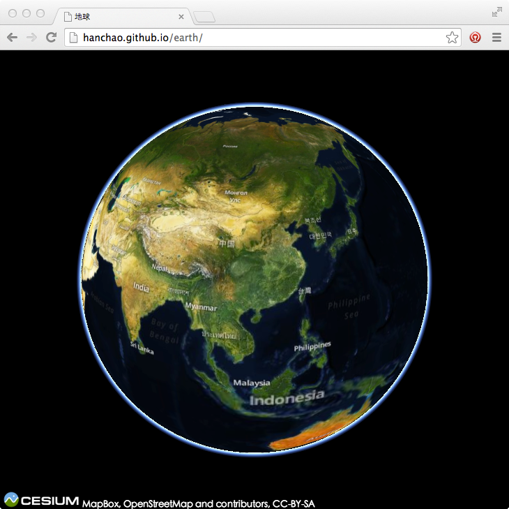
Cesium,一个基于WebGL的 JavaScript 绘图库, 通过其内部机制提供了这个能力。它支持3种不同的视图: 3D globe, 2D map,和 2.5D Columbus View ,从一种到另一种转换只需要一行代码。 画任何类型的形状,突出显示特定的地区以及使用鼠标或触摸与地图交互,都相当简单。Cesium只有一个 JS 文件,可在包括手机在内的所有主流浏览器运行。
主页:http://cesiumjs.org/ 已被墙,请自行翻墙
代码:https://github.com/AnalyticalGraphicsInc/cesium
Cesium的API简洁、文档比较丰富,根据 Getting Started 即可快速实现三维地球。
-
下载
下载地址:https://github.com/AnalyticalGraphicsInc/cesium/releases,当前最新版本为b26。
-
部署
将下载的压缩包解压,里面有个HelloWorld.html,直接用浏览器打开是无法使用的。
这里需要把整个目录拷贝到你web服务器(IIS、Apache等)中。
如果你安装了python,你可以cd到Cesium目录下,python -m SimpleHTTPServer运行简易的web服务器。
-
运行
打开支持WebGL的浏览器(Chrome),进入http://localhost:8000/HelloWorld.html,即可看到有包含bing影像数据的地球。
-
自定义图层
看看HelloWorld.html里面都写了什么,很简单就这么一句代码。
var cesiumWidget = new Cesium.CesiumWidget('cesiumContainer');
如果显示自定义图层呢,只需要几行代码而已。通过查看文档,可以看到CesiumWidget有个imageryProvider参数,默认使用bing的数据。
换个mapbox的数据,就这么几行
 var osm = new Cesium.OpenStreetMapImageryProvider({
     url : 'https://a.tiles.mapbox.com/v3/examples.map-qfyrx5r8/',
  	  credit : 'MapBox, OpenStreetMap and contributors, CC-BY-SA'
 });

 var cesiumWidget = new Cesium.CesiumWidget('cesiumContainer', {
     imageryProvider : osm});
可参见 我的demo